Web Configuration
Accessing the Web Interface
The TK804 series routers have a built-in web server for configuration.
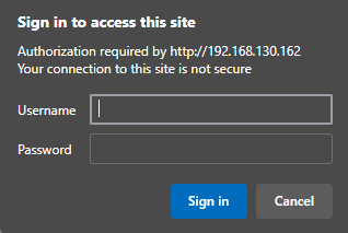
Open http://192.168.2.1 in your browser.
Enter the user name and password (default values printed on the label) and confirm with Login.
⚠️ For security reasons, the password should be changed after the first login.
Choose a password with at least 10 characters, including:
uppercase and lowercase letters
numbers
special characters
💡The router allows parallel access for up to four users via the web interface.
However, simultaneous configuration by multiple users should be avoided.
After successful login, the router web interface appears:
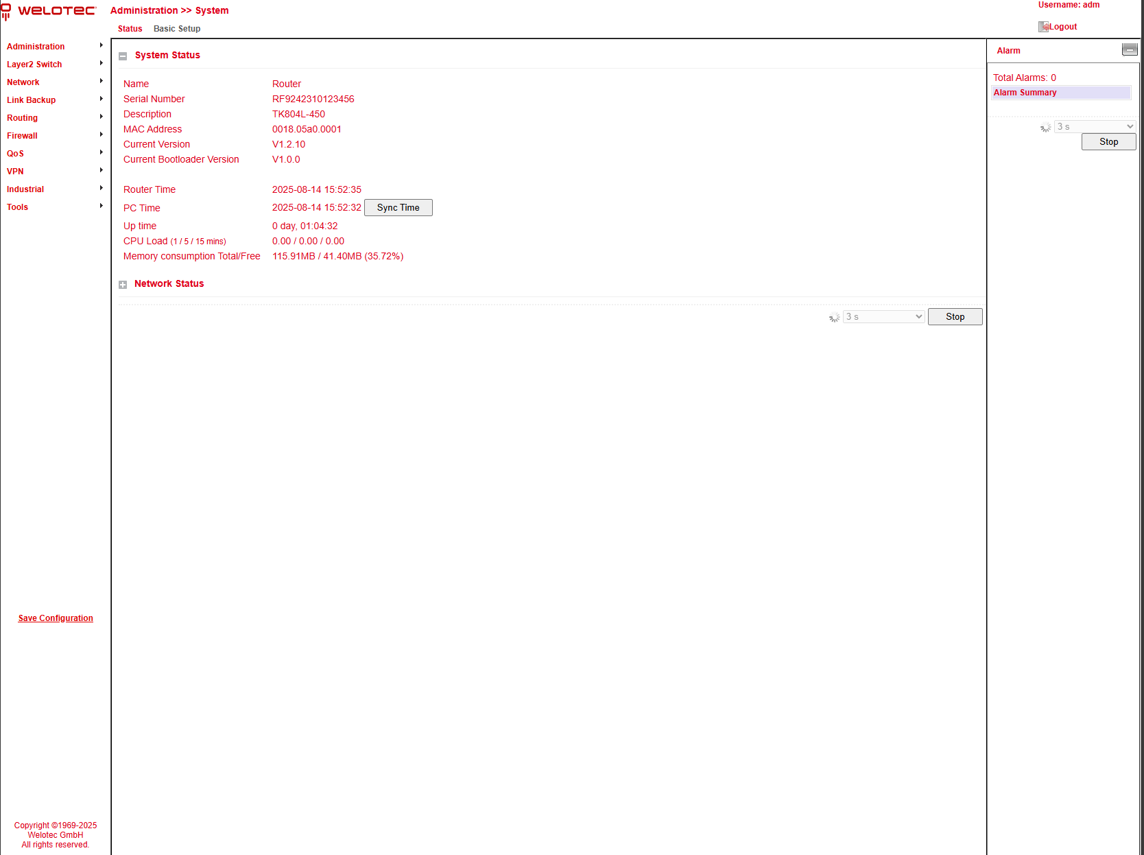
The web interface of the TK804L-450 is divided into four areas:
Main navigation (left) – e.g., Administration, Network.
Detail navigation (top) – e.g., Status (active), Basic Setup.
Main content area (center) – shows status and configuration options.
Alarm area (right) – shows active alarms.
Administration
On the left side you will find the menu item Administration.
Clicking it with the mouse opens a submenu.
This area contains the status overview and administration settings for the router.
⚠️ With restricted user rights (not administrator), some menu items are missing.
Restricted users cannot configure the router, the Apply & Save option is unavailable,
and several configuration options are hidden.

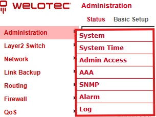
System
Status
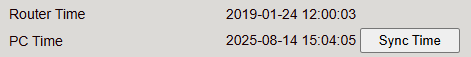
Under Administration > System > Status you will find the most important status information of the router at a glance.
With the Sync Time button, the router time can be synchronized with the time of the connected PC.

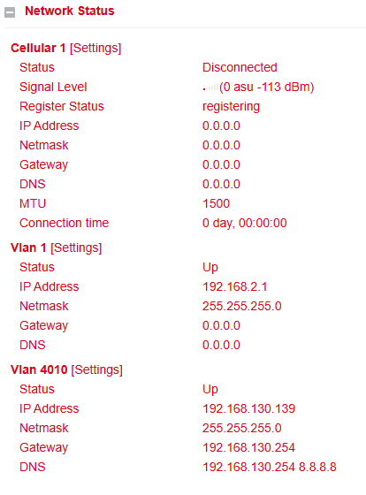
Below the system status, you will find the Network Status section.
By clicking on the gray [+] symbol, details of the individual network interfaces will expand.
Here you can see all relevant information about each interface.
⚠️ By clicking on [Settings] next to an interface (e.g., Cellular 1), you can directly access its configuration page.
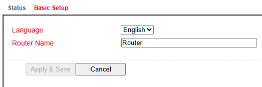
Basic Setup
Under Administration > System > Basic Setup you can configure:
Language – currently only English is supported.
Router name – choose a meaningful, unique name for easier identification.
System Time
To ensure correct coordination between the TK804L-450 router and other devices, the system time must be consistent across all components.
Under Administration > System Time you can configure:
Manual time setting
Automatic synchronization via a time server using the Simple Network Time Protocol (SNTP)
NTP server function – allows connected devices to obtain the current time from the router
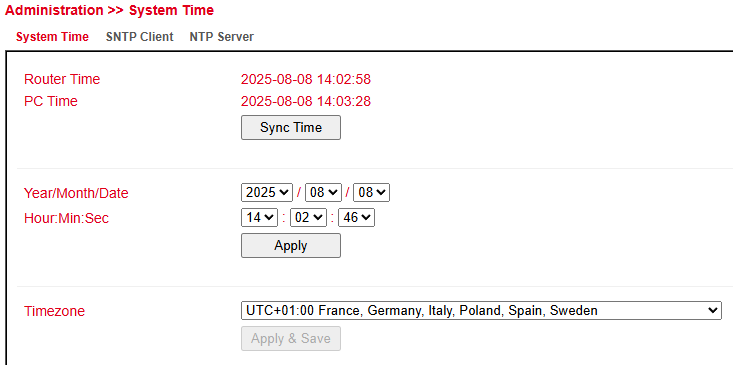
System Time Configuration
Under Administration > System Time you will find an overview and local settings for the system time of the router.
With Sync Time, the router time can be synchronized with the time of the connected PC.
Time and date can also be set manually.
Under Timezone, the current time zone can be selected.
The default is **UTC+1** (Germany, Austria, Switzerland).
SNTP Client
SNTP (Simple Network Time Protocol) is used to synchronize the clocks of network devices.
It provides mechanisms to synchronize time across a subnet, a network, or the Internet.
Typical accuracy: 1–50 ms, depending on the synchronization source and routers.
Goal: Ensure that all devices in a network share the same clock, so distributed applications run consistently.
Under Administration > System Time > SNTP Client you can configure the router to update its time from a public or private time server.
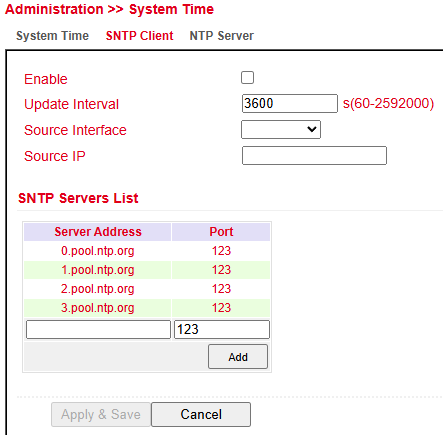
⚠️ Before setting up an SNTP client:
Verify that the selected SNTP server is reachable.
If using a domain name, ensure that the DNS server is configured correctly for name resolution.
You can configure either a Source Interface or a Source IP.
After a successful update, the following entry will appear under Administration > Log:

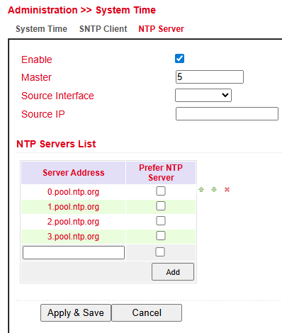
NTP Server
The settings for the time server are located under Administration > System Time > NTP Server.
In this mode, the TK804L-450 can act as a time server for connected devices.
Master (Stratum): Defines the accuracy level of the server.
Range: 2–15
Lower values indicate proximity to a highly accurate time source (e.g., atomic or radio clock).
Source Interface: Specifies the interface from which devices can request NTP.
Source IP: Alternative option for providing NTP service.
⚠️ Important:
NTP server and NTP client operate independently.
This means both require their own NTP service from the Internet.
To configure this, enter the address under Server Address (multiple entries possible).
Admin Access
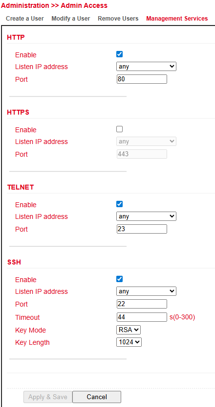
Management Services
Under Administration > Management Services you can configure access to the router via:
HTTP / HTTPS – web interface
Telnet / SSH – Command Line Interface (CLI)
HTTP
HTTP (Hypertext Transfer Protocol) is used for unencrypted access to the router’s web interface.
HTTPS
HTTPS (Hypertext Transfer Protocol Secure) uses SSL/TLS encryption to secure HTTP communication.
Telnet
Telnet allows access to the router’s Command Line Interface (CLI).
⚠️ Since Telnet is unencrypted, it is recommended to use SSH instead.
SSH
SSH (Secure Shell) provides encrypted CLI access to the router, comparable to Telnet but secure.
Configuration Options
For each service (HTTP, HTTPS, Telnet, SSH) you can configure:
Enable / Disable the service
Port – select the TCP port for the service
ACL Enable – activate access control:
Source Range and IP Wildcard define which IP addresses or ranges may access the router
SSH-specific options:
Timeout – inactive sessions are automatically closed after this period
Key Mode / Key Length – define encryption standard and key size
Other Parameters
Web login timeout – defines how long a web session remains active without input.
After the timeout expires, the user is logged out automatically.
User Management
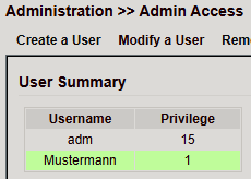
Under Administration > User Management you can configure the users that have access to the router.
The router distinguishes between Administrator and Standard User:
Administrator (adm) – created by the system, full rights
Standard User – created by the administrator, limited rights (monitoring only)
Create a User
Under Administration > User Management > Create a User you can create additional users.
Required fields:
Username
Password
Permission (Privilege):
1–14 → standard users (read-only)
15 → administrators (full access)
Under User Summary you will find a list of all users and their assigned privileges.
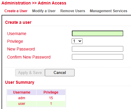
⚠️ Password policy:
Use at least 8 characters, including uppercase/lowercase letters, numbers, and special characters.
The username root is reserved for the operating system.
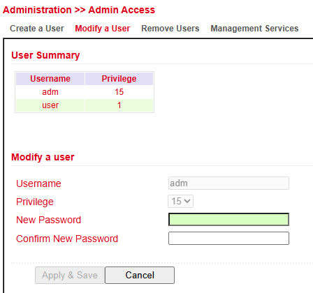
Modify a User
To change user settings, go to Administration > User Management > Modify a User.
Here you can update permissions and passwords.
In User Summary, select a user and edit them under Modify a User.
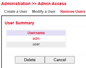
Remove Users
Under Administration > User Management > Remove Users you can delete accounts.
Select the user in User Summary.
Click Delete to remove the account.
AAA
AAA (Authentication, Authorization, Accounting) is a framework for managing network access:
Authentication → controls whether a user may access the device or network
Authorization → defines which services or resources the user may access
Accounting → logs all access events and resource usage
Notes:
Not all AAA services must be enabled; one or two can be used as needed.
AAA typically follows a client–server architecture.
The TK804L-450 acts as an AAA client and supports:
RADIUS
TACACS+
LDAP
RADIUS
RADIUS (Remote Authentication Dial-In User Service) is a client–server protocol used for authentication, authorization, and accounting.
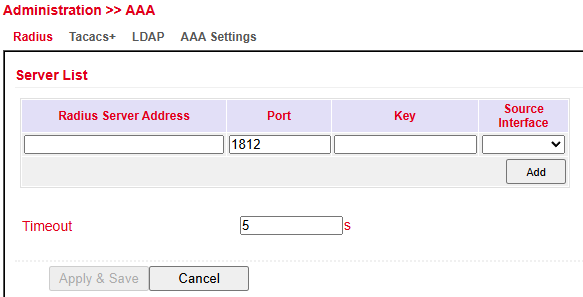
You can configure:
FQDN or IP address of the RADIUS server
Port
Shared Key
Source Interface
TACACS+
TACACS+ (Terminal Access Controller Access Control System) is a client–server protocol used for authentication, authorization, and accounting.
It provides communication between AAA servers and a Network Access Server (NAS).
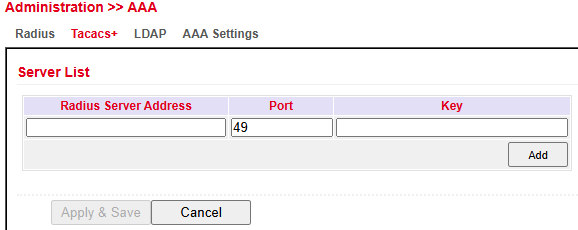
You can configure:
Server Address
Port
Shared Key
LDAP
LDAP (Lightweight Directory Access Protocol) is a protocol based on the client–server model, suitable for querying and modifying information from directory services.
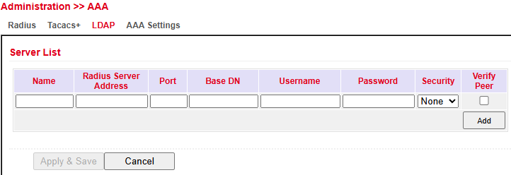
Enter the required connection details for your LDAP server here.
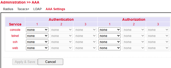
AAA Settings
The AAA Settings page lets administrators configure Authentication and Authorization for different management services: Console, Telnet, SSH, and Web.
Authentication: Verifies user identity. Up to three methods (e.g., Local, RADIUS, TACACS+, LDAP) can be set in order of preference.
Authorization: Controls user permissions after authentication. Also supports up to three methods.
None means no AAA is applied.
Apply & Save stores the changes; Cancel discards them.
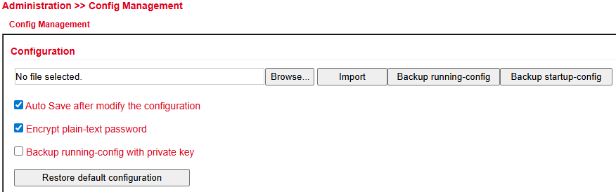
Config Management
Under Administration > Config Management you can:
Save the current configuration
Import an existing configuration
Reset the router to factory defaults
Importing an Existing Configuration
Click Browse… and select a configuration file.
Click Import to upload it.
After successful import, restart the router to activate the configuration.
Saving an Existing Configuration
Backup running-config → saves the current configuration including unconfirmed changes.
Backup startup-config → saves the configuration without unconfirmed changes.
Automatic Saving
If Auto Save after modify the configuration is checked:
All changes are applied immediately and persist after reboot.
If not checked:
Changes will be lost after reboot unless saved manually via Save Configuration (bottom left navigation).
Reset to Factory Defaults
Click Restore default configuration to reset the router to its default settings.
Encrypt Passwords in the Configuration File
Enable Encrypt plain-text password to prevent passwords from being displayed in clear text.
Back Up Running-Config with Private Key
Enable Backup running-config with private key to include imported private keys from certificate management in the backup.
SNMP
SNMP (Simple Network Management Protocol) is an IETF-standard protocol used to monitor and control network elements such as routers, servers, switches, printers, and computers from a central station.
SNMP defines the structure of the data packets and the communication flow.
It was designed so that any network-capable device can be integrated into monitoring.
Communication occurs between monitored devices (agents) and the monitoring station (manager).
SNMP Configuration
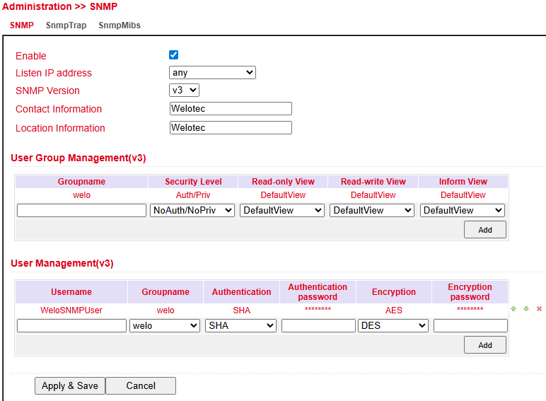
The TK804L-450 supports SNMP v1, v2c, and v3.
SNMPv1 / v2c: use a community name for authentication with read-only or read-write rights.
The IP address for the SNMP service can be selected under Listen IP address.

SNMPv3: uses username/password authentication and provides group management.
This allows individual users to be authorized more precisely compared to v1/v2.
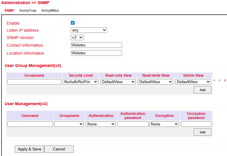
Supported in SNMPv3:
Authentication → SHA or MD5
Encryption → AES or DES
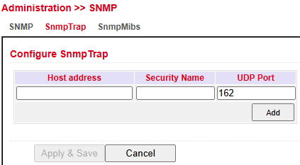
SNMP Trap
An SNMP Trap server can be configured.
This allows the router to actively send SNMP messages to the management server instead of waiting for requests.
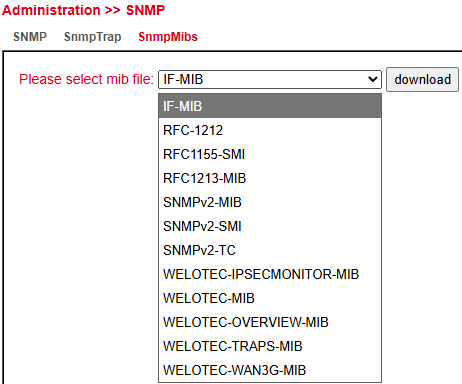
SNMP MIBs
The SNMP MIB files for monitoring the router can be downloaded and used for evaluations.
Select the desired MIB file and click the Download button.
Reading SNMP MIBs with SNMPWALK
Configure SNMP on the router:
Run SNMPWALK on a Linux computer, for example:
snmpwalk -v3 -u WeloSNMPUser -l AuthPriv -a SHA -A 123456789 \
         -x AES -X 123456789 10.255.229.10

snmpwalk -v3 -u WeloSNMPUser -l AuthPriv -a SHA -A 123456789 \
         -x AES -X 123456789 udp6:[2a02:d20:8:c01::1]
Download MIBs from TK804L-450
Install MIBs locally
mkdir -p ~/.snmp/mibs
cp Downloads/WELOTEC* ~/.snmp/mibs/


 Available MIBs:

 -   WELOTEC-PORTSETTING-MIB
 -   WELOTEC-SERIAL-PORT-MIB
 -   WELOTEC-SYSTEM-MAN-MIB
 -   WELOTEC-WAN3G-MIB
Start SNMPWALK using the MIBs
snmpwalk  -m +WELOTEC-MIB -v3 -u WeloSNMPUser -l AuthPriv \
          -a SHA -A 123456789 -x AES -X 123456789 192.168.2.1 WELOTEC


Example Output

WELOTEC-MIB::ihOverview.1.0 = STRING: "TK804L-450"
WELOTEC-MIB::ihOverview.2.0 = STRING: "RF9151408241109"
WELOTEC-MIB::ihOverview.3.0 = STRING: "2011.09.r7903"
WELOTEC-MIB::ihOverview.4.0 = STRING: "1.0.0.r9919"
WELOTEC-MIB::ihWan3g.1.1.1.0 = INTEGER: 3
Alarm
Status
The Alarm Status page shows an overview of all triggered alarms.
Alarm Input
In the Alarm Input menu, you can define which alarm messages the router should output.
By setting or removing checkmarks, each alarm can be enabled or disabled.
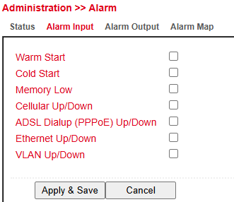
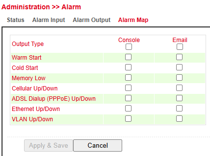
Available alarm messages:
Parameter |
Description |
|---|---|
Warm Start |
Warm restart/reboot of the router |
Cold Start |
Cold start = booting the router after power-off |
Memory Low |
Low memory condition |
Cellular Up/Down |
Mobile connection (GPRS/UMTS/LTE) connected or disconnected |
ADSL Dialup (PPPoE) Up/Down |
ADSL dialup connected or disconnected |
Ethernet Up/Down |
Ethernet interface connected or disconnected |
VLAN Up/Down |
VLAN connection established or disconnected |
Alarm Map
In the Alarm Map you can define whether alerts are displayed in the web interface.
Enable or disable the feature by checking the box.
Log
The Log menu displays the current router messages.
It contains information about:
Network status
Operational status
Configuration changes
ISP connection
IPSec / OpenVPN status
And more
Available options in the log section:
Option |
Description |
|---|---|
Clear Log |
Delete displayed log entries |
Download Log File |
Download current log file |
Download Diagnose Data |
Download diagnostic data file |
Clear History Log |
Delete log history |
Download History Log |
Download log history |
System Log
In System Log you can specify a syslog server to which router logs are sent over the network.
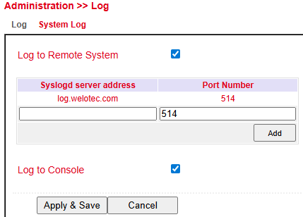
Syslog server address → Enter the host name (FQDN) or IP address of the syslog server.
Port → Default is 514 (standard syslog port).
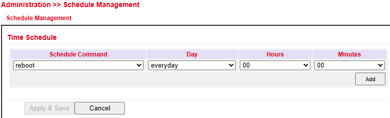
Schedule Management
Upgrade
Firmware updates can be performed in the Upgrade menu.
Firmware updates may include new features or bug fixes.
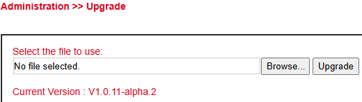
The currently installed firmware is displayed under Select the file to use.
Click Browse and select the firmware file (
.binor.pkg) previously downloaded.Click Upgrade to install the firmware.
⚠️ Note:
If the installed version is significantly older, the bootloader and the I/O board may need to be updated separately.
For details, please contact support.
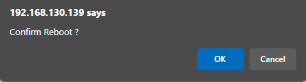
Reboot
The router can be restarted via Reboot.

⚠️ - Click OK to confirm the reboot.
Always save the configuration before restarting. Otherwise, unsaved changes will be lost.
Layer2 Switch
Status
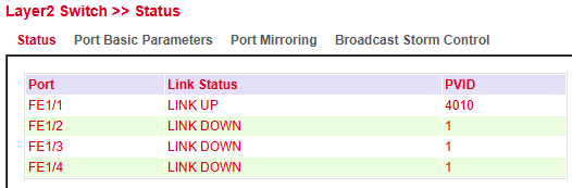
The Status section shows the link status and VLAN assignment (PVID) for each physical switch port.
Link Status → Displays if a port is active (LINK UP) or inactive (LINK DOWN)
PVID (Port VLAN ID) → Indicates the VLAN assigned to untagged traffic on the port
This helps to quickly identify active connections and verify VLAN configuration.
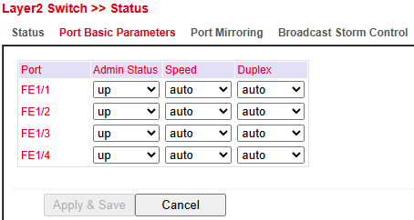
Port Basic Parameters
In Port Basic Parameters, you can configure each port with:
Admin Status → Enable/disable the port (up or down)
Speed → Auto-negotiation or fixed speed
Duplex → Auto, Full, or Half duplex
These settings allow performance optimization and device compatibility management.
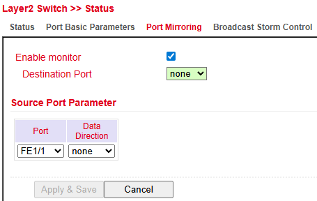
Port Mirroring
Port Mirroring allows monitoring of network traffic by copying packets from one or more source ports to a destination port.
Enable Monitor → Activates mirroring
Destination Port → Port to which mirrored traffic is sent (e.g., analysis tool)
Source Port Parameters:
Port → The monitored port
Data Direction → Ingress, Egress, or Both
This feature is used for diagnostics, intrusion detection, or performance analysis.
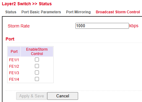
Broadcast Storm Control
The Broadcast Storm Control feature allows administrators to limit the rate of broadcast traffic per port to prevent network flooding.
Storm Rate → Sets the maximum allowed broadcast traffic rate (in kbps).
Enable Storm Control → Can be enabled individually for each port.
Activating this feature on selected ports helps maintain network stability during broadcast storms caused by misconfigured devices or loops.
Network
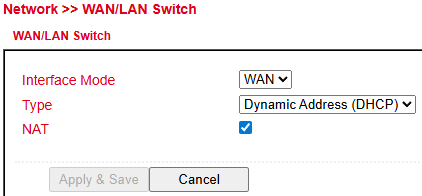
WAN/LAN Switch
The WAN/LAN Switch section defines the role and addressing behavior of the network interface.
Interface Mode → Select whether the interface operates as WAN or LAN.
Type → Defines the IP configuration mode:
Dynamic Address (DHCP) → Automatically obtains IP settings from a DHCP server.
Static Address → Manual configuration (not shown in image but typically supported).
NAT (Network Address Translation) → When enabled, private IP addresses are translated to a public IP for Internet access.
This configuration is essential for defining how the device integrates into the network and whether it routes traffic between private and public networks.
VLAN
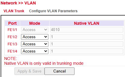
VLAN Trunk
The VLAN Trunk configuration assigns VLAN modes and native VLANs to individual ports.
Port → The physical Ethernet interface.
Mode →
Access → Port belongs to a single VLAN.
Trunk → Port carries traffic for multiple VLANs (not shown in image but typically supported).
Native VLAN → Only valid when the port is in Trunk mode; defines the VLAN for untagged traffic.
⚠️ Note: Native VLAN settings apply only when the port operates in Trunk mode.
This setting is critical for managing VLAN tags on networks with VLAN-aware devices.
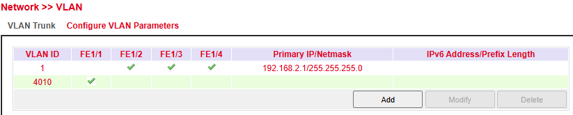
Configure VLAN Parameters
In this section you can define VLAN IDs, assign them to ports, and configure IP addressing for VLAN interfaces.
VLAN ID → Identifier for the VLAN (e.g., 1, 4010).
Port Membership → Assigns ports to the VLAN.
Primary IP / Netmask → Layer3 IP configuration for management or routing.
IPv6 Address / Prefix Length → Optional IPv6 configuration (empty in example).
Available Actions:
Add → Create a new VLAN.
Modify → Change VLAN settings.
Delete → Remove an existing VLAN.
This configuration is essential for network segmentation, traffic isolation, and improving security and performance.
Cellular
The Cellular interface provides mobile communication access.
With an inserted SIM card, the router can connect to the Internet via GPRS, EDGE, UMTS, or LTE, depending on the model.
Status
Under Status you find an overview of the current connection state (Connected / Disconnected).
Network Type → shown in the Status tab
IP Address → shown in the Network section
Modem area → shows signal level, RSRP, and RSRQ
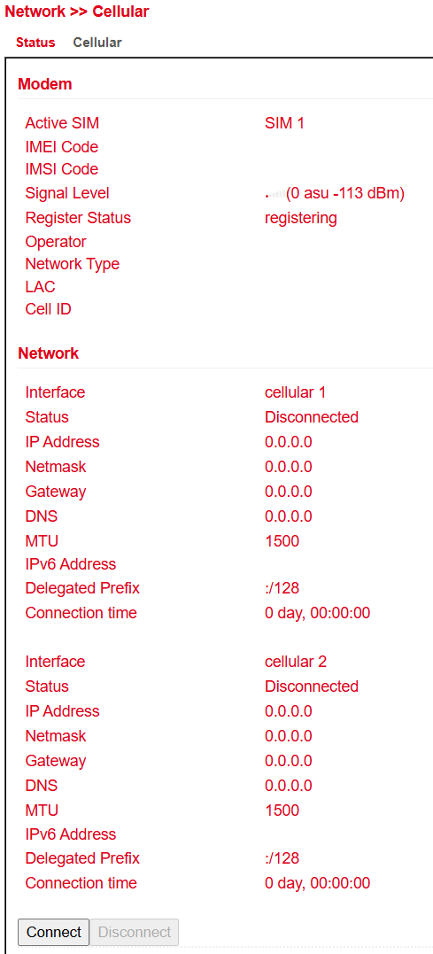
⚠️ In some cases, the router may not receive a valid DNS server from the provider.
Check the DNS entry:
If empty → no DNS assigned
If unusual (e.g.,
10.74.210.210→ Telekom internal DNS), adjust settings accordingly.
RSRP (Reference Signal Received Power)
RSRP is one of the most important indicators for assessing LTE reception quality.
It is measured directly by the device and used to determine the strongest cell.
RSRP (dBm) |
Grade |
Comment |
|---|---|---|
-50 to -65 |
1 (very good) |
Excellent reception – perfect |
-65 to -80 |
2 (good) |
Good reception – sufficient |
-80 to -95 |
3 (satisfactory) |
Stable, but not optimal |
-95 to -105 |
4 (sufficient) |
Acceptable, but speed restrictions / occasional drops possible |
-110 to -125 |
5 (poor) |
Very poor – connection barely possible |
-125 to -140 |
6 (insufficient) |
Extremely poor – likely no connection |
RSRQ (Reference Signal Received Quality)
RSRQ is a calculated ratio based on RSRP and RSSI, and is crucial for evaluating LTE quality.
Together with RSRP, it helps optimize antenna alignment for stationary use.
RSRQ (dB) |
Grade |
Comment |
|---|---|---|
-3 |
1 (very good) |
Optimal, no interference |
-4 … -5 |
2 (good) |
Minor interference, no impact |
-6 … -8 |
3 (satisfactory) |
Noticeable influence, but still stable |
-9 … -11 |
4 (sufficient) |
Significant interference, connection affected |
-12 … -15 |
5 (poor) |
Heavy interference, unstable connection |
-16 … -20 |
6 (insufficient) |
Severe interference, no usable connection |
⚠️ Many providers assign private IP addresses that are not directly routable from the Internet.
A successful or failed ping does not always indicate Internet reachability.
Cellular Configuration
Under Network > Cellular > Cellular you can configure mobile network access.
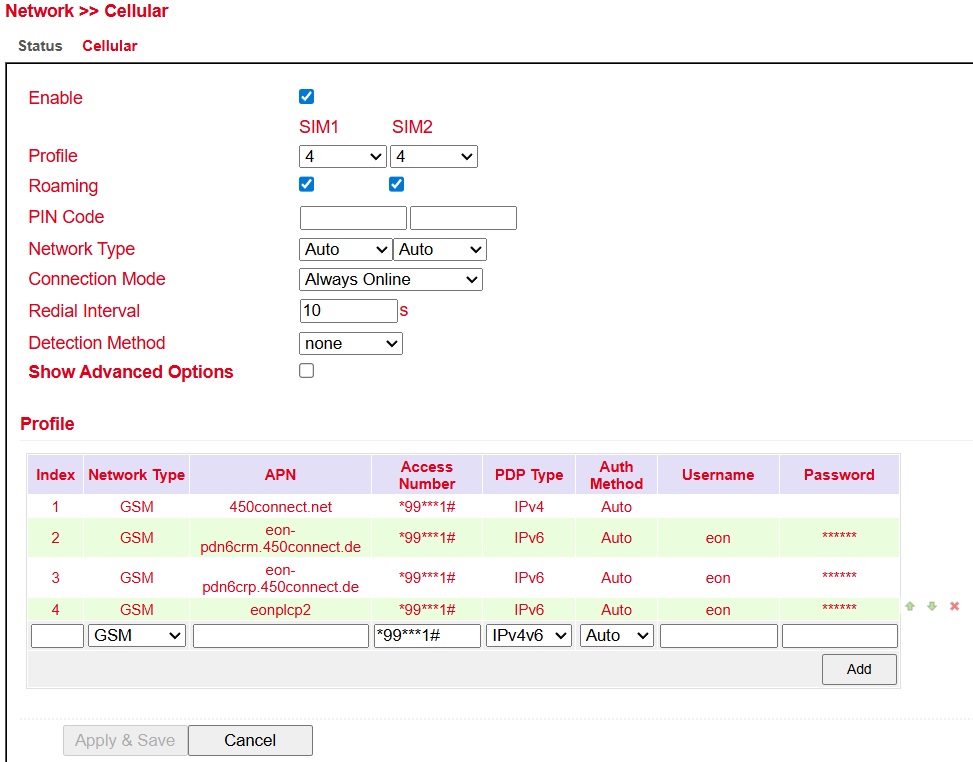
Parameter |
Description |
Default |
|---|---|---|
Enable |
Enable or disable the cellular interface |
Enabled |
Profile |
APN profile for SIM 1 and SIM 2 |
Auto / Auto |
Roaming |
Enable or disable roaming. ⚠️ Depends on provider – roaming may occur despite being disabled. |
Enabled / Enabled |
PIN Code |
SIM card PIN. ⚠️ Enter before inserting SIM card. |
Blank / Blank |
Network Type |
Auto / 2G (GPRS, EDGE) / 3G (UMTS, HSDPA, HSUPA, HSPA+) / 4G (LTE) |
Auto |
Connection Mode |
Always online or on-demand connection |
Always Online |
Redial Interval |
Interval for redialing |
10 seconds |
Detection Method |
How to check Internet connectivity (e.g., ICMP ping, DNS, HTTP) |
ICMP (Ping) |
Show Advanced Options |
Displays additional settings when enabled |
Disabled |
ADSL Dialup (PPPoE)
Status
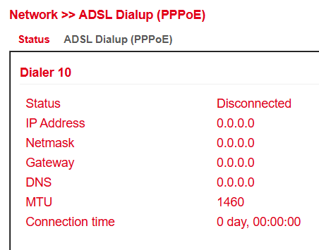
The TK804L-450 routers do not have a built-in ADSL modem.
For ADSL dial-up, connect an external ADSL modem to the WAN port.
⚠️ Ensure the DSL modem supports modern IP technologies for proper operation.
ADSL Dialup (PPPoE)
Here you can configure DSL dial-in via PPPoE.
The TK804L-450 does not have an integrated DSL modem, so an external modem is required.
The DSL modem should meet the following criteria:
VDSL2 / ADSL2 Ethernet modem
Annex A / B / M / J compatible
PPPoE bridge operation
IPv4 and IPv6 compatible
DSL standards:
ANSI T1.413 Issue 2
ITU G.992.1 A/B (G.dmt)
ITU G.992.2 (G.lite)
ITU G.992.3 (VDSL2)
ITU G.992.4 (G.HS)
ITU G.992.5 (ADSL2+)
⚠️ Ensure the modem is connected to the router before configuration.
The DSL modem should be attached to FE 0/1 or a defined VLAN port.
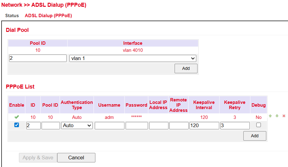
Dial Pool
The Pool ID defines the interface used for PPPoE dial-up.
PPPoE List
Parameter |
Description |
|---|---|
Enable |
Enable or disable the PPPoE entry |
ID |
Unique identifier for the entry |
Pool ID |
Pool ID created under Dial Pool for the interface used for the connection |
Authentication Type |
Auto, PAP, CHAP (usually set to Auto) |
Username |
Username provided by your ISP |
Password |
Password provided by your ISP |
Local IP Address |
Local IP address |
Remote IP Address |
IP address of the remote device (modem) |
Keepalive Interval |
Time interval for connection checks |
Keepalive Retry |
Number of retries if a connection check fails |
Debug |
Enables detailed logging |
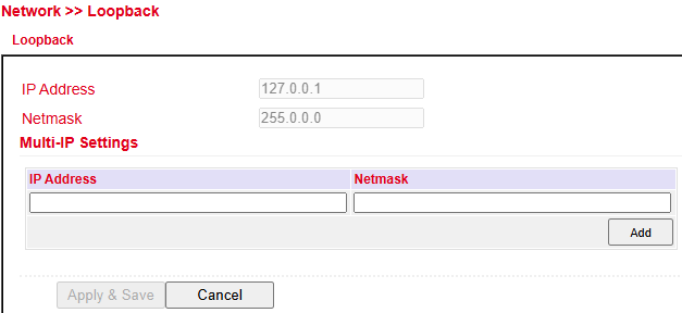
Loopback
Loopback Configuration
Under Network > Loopback you can configure additional loopback IP addresses.
⚠️ The default address 127.0.0.1 cannot be modified.
DHCP
Dynamic Host Configuration Protocol (DHCP) automatically assigns network configuration to clients.
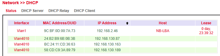
Status
Under Services > DHCP > Status you can view which clients are currently connected to the router and on which interface.
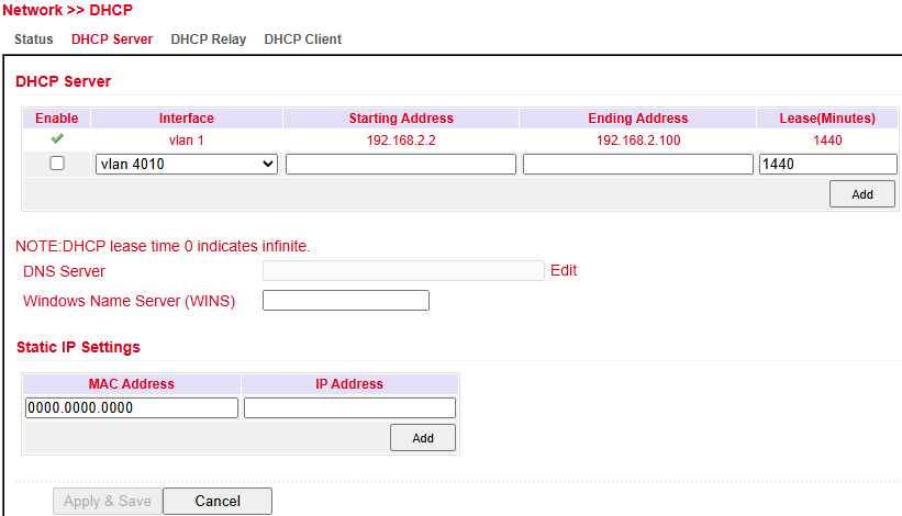
DHCP Server
Under Services > DHCP > DHCP Server you can configure the DHCP server:
Select the interface
Define start and end IP address
Configure lease time
With Static IP Settings, an IP address can be permanently assigned to a specific MAC address.
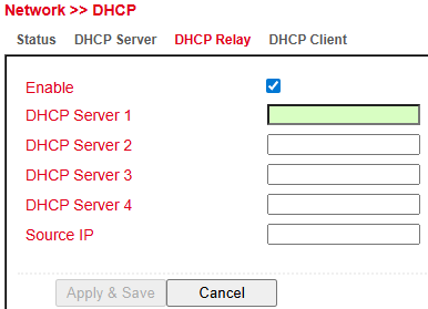
DHCP Relay
Under Services > DHCP > DHCP Relay you can specify remote DHCP servers, which then provide IP management for connected networks.
Enable this feature with the Enable checkbox.
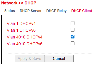
DHCP Client
Under Services > DHCP > DHCP Client, the router itself can obtain an IP address from a DHCP server.
Select the interface to be configured via DHCP (varies by router model).
DNS
Domain Name System (DNS) is one of the most important services in IP networks.
Its main purpose is name resolution:
A client queries a domain name (e.g.,
welotec.com).DNS resolves the domain to the corresponding IP address (e.g.,
192.168.2.1).The IP address allows the client to reach the correct server.
This works similar to a telephone directory, where a name is resolved into a number.
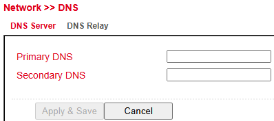
DNS Server
Under Services > DNS > DNS Server you can configure up to two DNS servers.
These apply to all interfaces unless a different DNS server is assigned via DHCP.
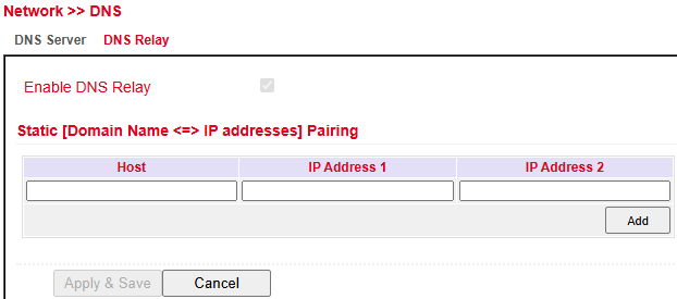
DNS Relay
Under Services > DNS > DNS Relay you can add manual DNS resolutions.
Click Add to create an entry.
Click Apply & Save to confirm changes.
DDNS (Dynamic DNS)
Dynamic DNS (DDNS) updates domain entries automatically after a public IP address changes.
This ensures the device is always reachable under the same domain name, even if the public IP changes.
Example providers: DynDNS, NoIP
DDNS Status
Under Services > DDNS > Status, the currently active DDNS services are displayed.
DDNS Configuration
Under Services > DDNS > DDNS you can configure a new service.
⚠️ A DDNS service must first be created in DDNS Method List, then assigned to an interface under Specify A Method To Interface.
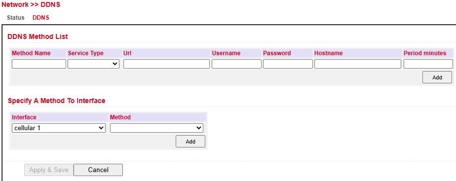
DDNS Method List
Parameter |
Description |
|---|---|
Method Name |
Freely selectable name for the service |
Service Type |
Predefined DDNS services available. Use Custom if not listed |
URL |
Required only for Custom type. Full service URL including username and password. |
Username |
Username for the DDNS provider |
Password |
Password for the DDNS provider |
Hostname |
Domain name used |
Period (minutes) |
Update interval, range 1–999999 minutes |
Assign Method to Interface
Parameter |
Description |
|---|---|
Interface |
Router interface whose IP should be updated via DDNS |
Method |
DDNS service created under DDNS Method List |
⚠️ Note: You need an account with a DDNS provider (may be chargeable). Configure this account before use.
SMS
Introduction
The TK804L-450 can be controlled via SMS commands.
Supported actions include:
Querying device status
Starting/stopping dial-up
Restarting the router
Status Query / Restart
Open the Services > SMS menu.
Check Enable to activate the feature.
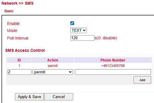
In SMS Access Control, enter phone numbers allowed to send SMS commands.
Format:
4917123456789(no0049or+49)Action: permit
Example:
Send SMS with text show → router replies with its current status.
Link Backup
The TK804L-450 supports dual Internet connectivity (wired + cellular) to increase availability.
The router regularly checks the primary Internet connection.
On failure, it switches automatically to the secondary (cellular) connection.
Once the primary connection is restored, the router switches back automatically.
⚠️ Prerequisite: Cellular Internet access must be configured.
The router is preconfigured for T-Mobile SIM cards, so normally no additional steps are required.
SLA
SLA Monitoring checks the availability of peers within the network using ping tests.
Defined destinations are continuously pinged, and the line state is shown as up or down.
Configure SLA under Link Backup > SLA > SLA.
Parameter |
Description |
|---|---|
Index |
Freely selectable, used to identify the entry |
Type |
|
Destination Address |
Address to be pinged (should be highly available, e.g., Google DNS |
Data size |
Packet size of a ping (default: 56 bytes) |
Interval (s) |
Interval in seconds between pings |
Timeout (ms) |
Timeout for each ping |
Consecutive |
Number of retries if a ping fails |
Life |
|
Start-time |
|
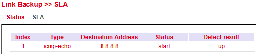
Status
SLA status shows whether the ping is successful (Detect result up) or unsuccessful (Detect result down).

Track
Configure a Track object under Link Backup > Track > Track.
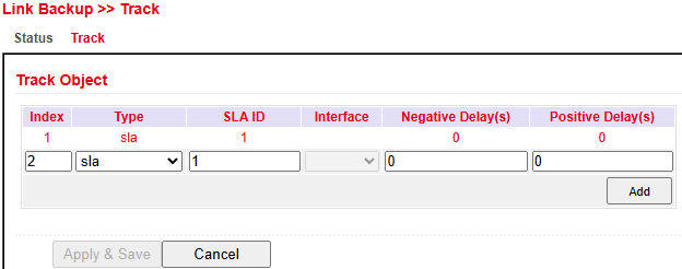
Parameter |
Description |
|---|---|
Index |
Freely selectable, identifies the entry |
Type |
|
SLA ID |
SLA index previously created |
Interface |
Not used when type = SLA |
Negative Delay (s) |
Delay before switching to backup if the main connection fails |
Positive Delay (s) |
Delay before switching back to the main connection once available |
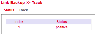
Status
The Track status indicates whether the monitored connection is up.
Check status under Link Backup > Track > Status.
VRRP
In IP networks, all clients rely on a common gateway. If this gateway fails, communication to external networks (e.g., the Internet) is interrupted.
VRRP (Virtual Router Redundancy Protocol) solves this by allowing multiple routers to act as one virtual router:
One router is the master (active gateway).
Others remain in backup mode.
If the master fails, a backup automatically takes over.
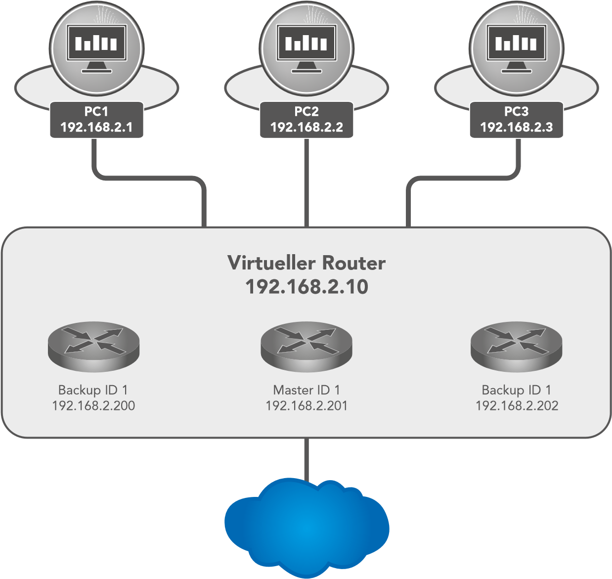
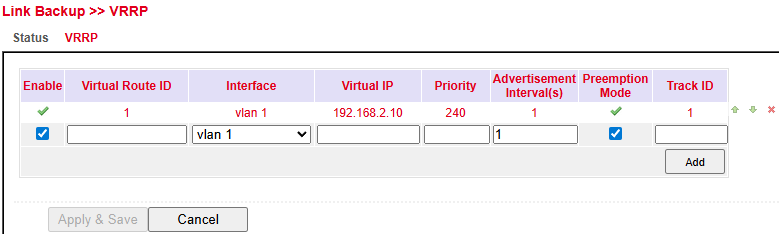
Parameter |
Description |
|---|---|
Enable |
Enable/disable VRRP |
Virtual Router ID |
Group ID – must match across all routers in the VRRP group |
Interface |
LAN interface used |
Virtual IP |
Shared virtual router IP, must match across all routers in the group |
Priority |
0–254 → higher value = higher priority (highest becomes master) |
Advertisement Interval(s) |
Interval in seconds for VRRP hello messages |
Preemption Mode |
If enabled, a router with higher priority takes over as master automatically |
Track ID |
Track object used to monitor connection health |
Status
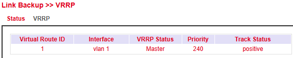
Parameter |
Description |
|---|---|
Virtual Router ID |
Router group identifier |
Interface |
LAN interface |
VRRP Status |
Current role → master or backup |
Priority |
Priority of the router |
Track Status |
Connection check result |
Interface Backup
Interface Backup allows automatic failover between interfaces:
If the main interface fails, traffic switches to a backup interface.
Configure under Link Backup > Interface Backup > Interface Backup.
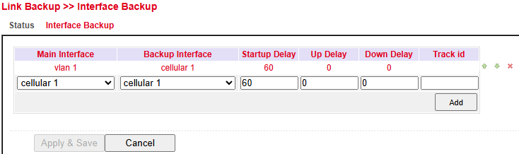
Parameter |
Description |
|---|---|
Main Interface |
Defines the main (primary) interface |
Backup Interface |
Defines the backup interface |
Startup Delay |
Delay in seconds after system startup before monitoring begins |
Up Delay |
Delay before switching back to the main interface |
Down Delay |
Delay before switching to backup interface |
Track ID |
Track index linked to a previously created Track entry |
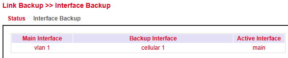
Status
The status page shows:
Which interfaces are configured as main/backup
Which interface is currently active
Routing
Routing determines how data packets are transported between networks.
Routers use routing tables to select the best path.
On the Internet, multiple paths may exist, but data is reassembled correctly at the destination.
Static Routing
Static Routing defines fixed routes to specific networks or hosts.
Configure under Routing > Static Routing > Static Routing.
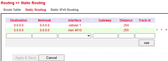
Parameter |
Description |
|---|---|
Destination |
Destination host, subnet, or network. Default route = |
Netmask |
Subnet mask used with destination. Example: host = |
Interface |
Network interface for the route (e.g., |
Gateway |
Next-hop IP address |
Distance |
Priority/metric for the route – lower values take precedence if multiple routes exist |
Track ID |
Optional link to a Track object for monitoring |
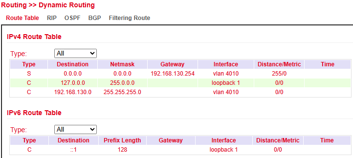
Route Table
The routing table can be viewed under:
Routing > Static Routing > Routing Table and
Routing > Dynamic Routing > Routing Table
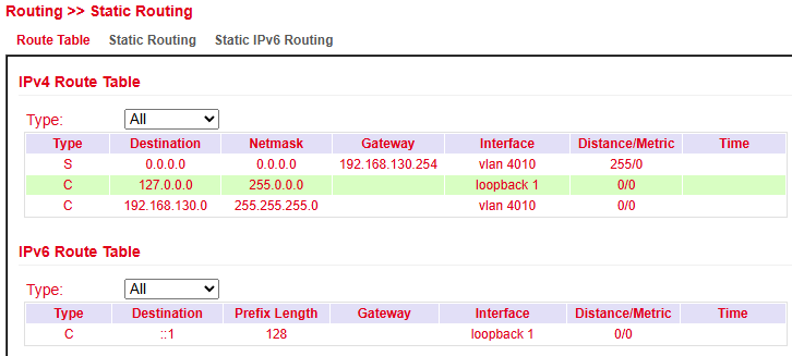
Parameter |
Description |
|---|---|
Type |
|
Destination |
Destination host, subnet, network, or default route ( |
Netmask |
Used with destination to define route scope. Example: |
Gateway |
Next-hop IP address. |
Interface |
Interface used for the route (e.g., |
Distance/Metric |
Route priority. Lower = higher priority. If multiple routes exist, the one with the lowest metric is preferred. |
Time |
Duration the route has been active. |
Static IPv6 Routing
Static IPv6 routes can be defined to direct traffic through specific network paths.
This is essential in multi-interface or segmented networks.
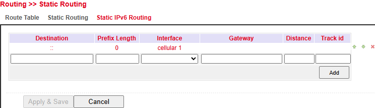
Parameter |
Description |
|---|---|
Field |
Destination IPv6 network or host address. |
Prefix Length |
Subnet size (e.g., |
Interface |
Outgoing interface (e.g., |
Gateway |
Next-hop IPv6 address. |
Distance |
Administrative distance (lower = preferred). |
Track ID |
(Optional) ID for route tracking / failover. |
Actions:
Add → Create new static IPv6 route.
Apply & Save → Save changes.
Cancel → Discard changes.
Dynamic Routing
Dynamic routing allows routes to be learned automatically by routing protocols.
Unlike static routing, paths are updated dynamically during operation.
Route Table
Viewable under:
Routing > Dynamic Routing > Routing Table
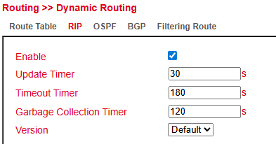
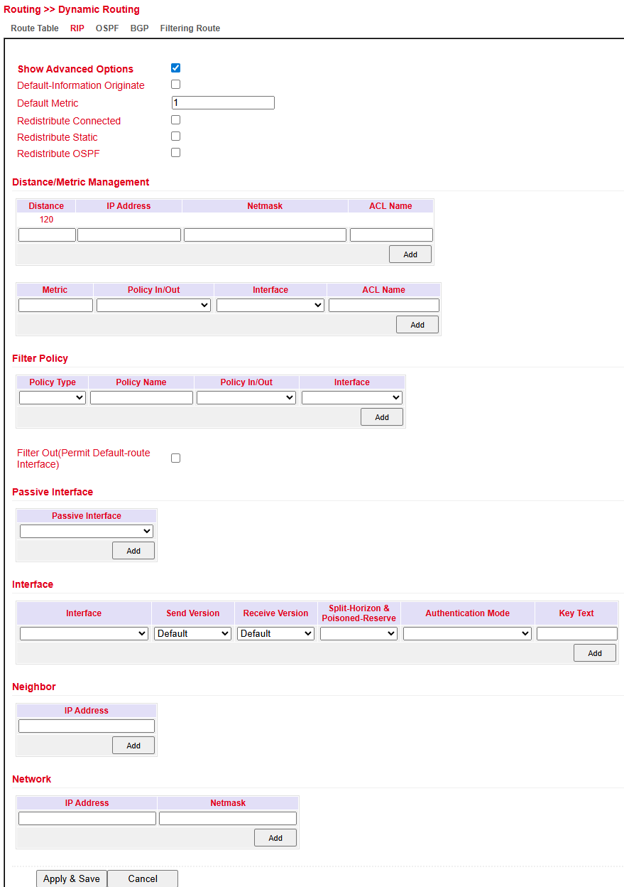
RIP
RIP (Routing Information Protocol) uses a distance vector algorithm to share routes.
Each router advertises known routes to its neighbors.
The best route is chosen based on hop count (max. 15 hops).
Configure under: Routing > Dynamic Routing > RIP
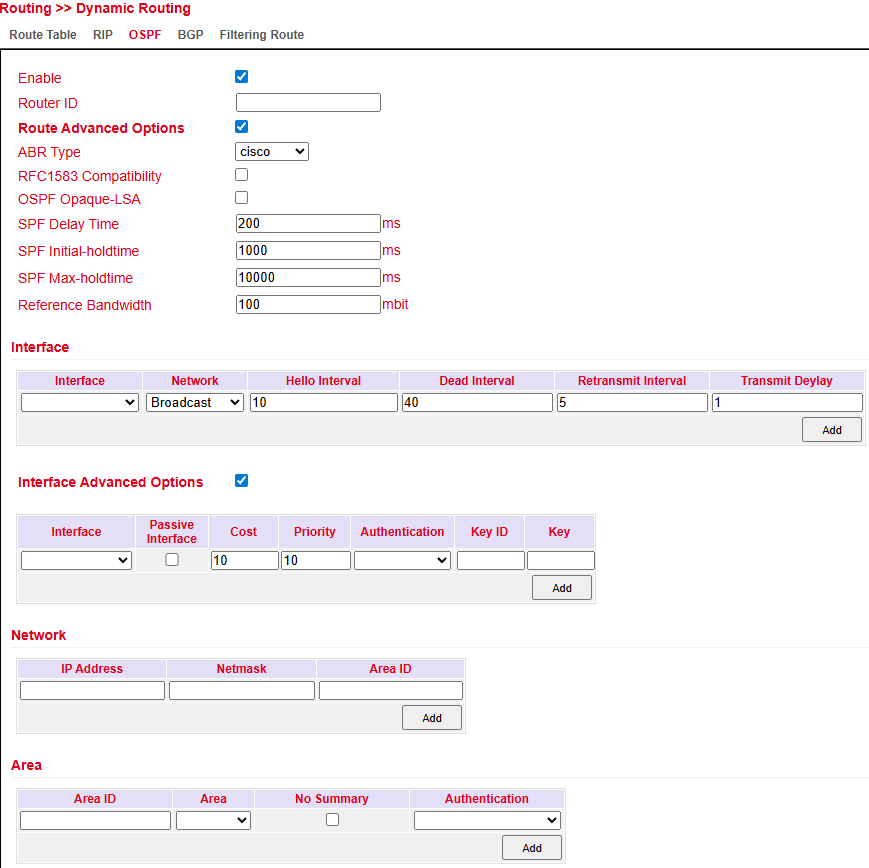
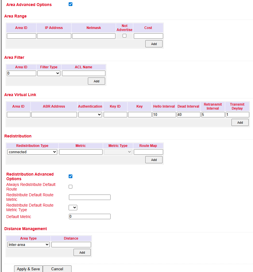
OSPF
OSPF (Open Shortest Path First) uses a link-state algorithm.
Supports hierarchical networks.
Allows multiple equal-cost paths simultaneously.
Reacts quickly to topology changes and uses bandwidth efficiently.
Configure under: Routing > Dynamic Routing > OSPF
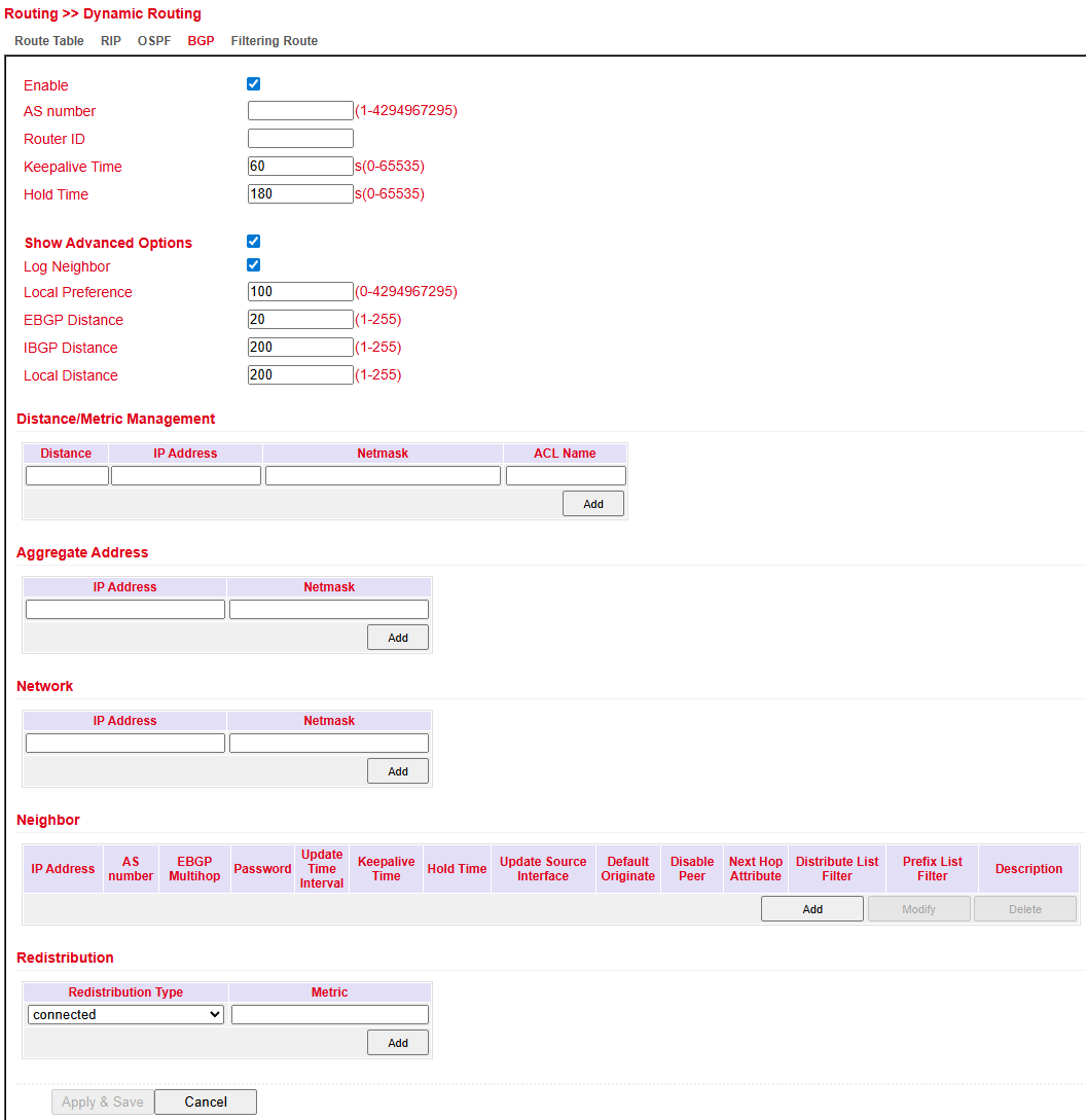
BGP
BGP (Border Gateway Protocol) is the Internet’s main routing protocol.
Connects autonomous systems (AS), typically Internet Service Providers.
Uses path vector routing.
Routing decisions often consider business policies in addition to technical metrics.
Configure under: Routing > Dynamic Routing > BGP
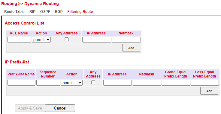
Filtering Route
Under Routing > Dynamic Routing > Filtering Route you can configure routing filters.
Filters define which routes are advertised or accepted.
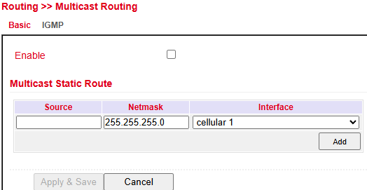
Multicast Routing
Basic
Configure under: Routing > Multicast Routing > Basic
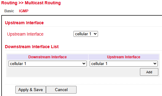
IGMP
IGMP (Internet Group Management Protocol) configuration:
Upstream Interface → Select the interface distributing the multicast.
Downstream Interface List → Select downstream interfaces for multicast traffic.
Interfaces vary depending on the router model.
Firewall
ACL
The Access Control List (ACL) controls usage and administration by defining which computers or networks can access the router or networks behind it.
ACL rules analyze and manage incoming and outgoing data packets according to defined rules.
Rules can be based on source/destination IP addresses, TCP/UDP port numbers, and more.
Two types of ACL are supported:
Standard ACL → Allow/deny communication from/to a network.
Extended ACL → More granular options (e.g., restrict HTTP, FTP, Telnet).
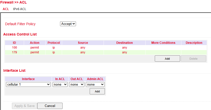
Overview of existing ACL rules.
Click Add to create a new ACL.
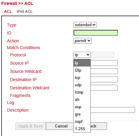
ACL Parameters
Parameter |
Description |
|---|---|
Type |
|
ID |
Default: 100 (preconfigured). Additional IDs can be freely assigned. |
Action |
|
Protocol |
Protocol(s) to match |
Source IP |
Source IP address or network (e.g., |
Source Wildcard |
Wildcard of source subnet mask (e.g., |
Destination IP |
Destination IP address or network (e.g., |
Destination Wildcard |
Wildcard of destination subnet mask (e.g., |
Description |
Optional text description |
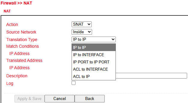
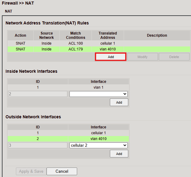
NAT
Network Address Translation (NAT)
NAT modifies address information in data packets to connect different networks.
It is configured under Firewall > NAT.
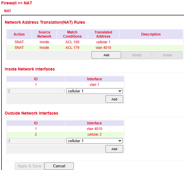
NAT Types
Type |
Action |
|---|---|
SNAT |
Rewrites the source IP address (LAN → WAN) |
DNAT |
Rewrites the destination IP address (WAN → LAN) |
1:1 NAT |
Maps one IP address to another (one-to-one translation) |
Inside/Outside Interfaces
Inside = LAN interface
Outside = WAN interface
Translation Types
Type |
Description |
|---|---|
IP to IP |
Translate one IP to another |
IP to Interface |
Translate IP to an interface’s address |
IP Port to IP Port |
Translate IP:Port combination to another |
ACL to Interface |
Translate address according to ACL into an interface address |
ACL to IP |
Translate address according to ACL into another IP |
Example: Case 1 – SNAT (Router as Internet Gateway)
The TK804L-450 translates private LAN IPs into a public IP for Internet access.
⚠️ This is the default factory setting.
Steps:
Create an ACL rule under Firewall > ACL:
Assign an ID.
Enter source IP/network and wildcard mask.
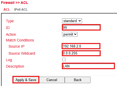
Configure the SNAT rule.
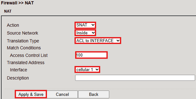
Define the Inside (LAN) and Outside (WAN) interfaces.
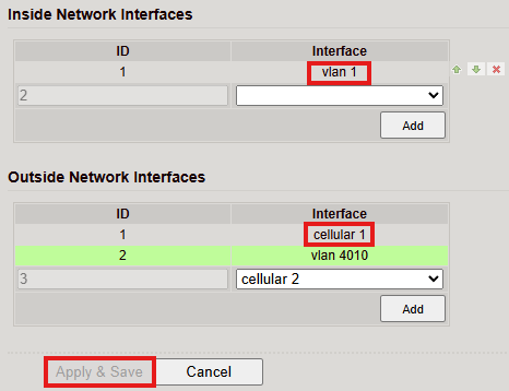
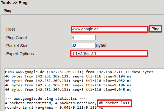
Test access with Ping under Tools > Ping.
Use the Expert option:
-I 192.168.2.1(capital i) to ensure ping originates from LAN interface.
Example: Case 2 – DNAT (Port Mapping / Port Forwarding)
DNAT (also known as Port Mapping/Forwarding) is used to make internal services (e.g., web servers) accessible from the Internet.
Configuration steps follow the same pattern:
Define ACL (optional, depending on policy).
Configure DNAT rule with desired port mapping.
Assign interfaces.
Requirements
Public IP address in the mobile network (or also for wired Internet connections).
(Note: Many mobile operators offer business tariffs with public IPs, e.g. T-Mobile IP VPN or Vodafone CDA. Some providers also supply public IPs via standard SIM cards.)
Port Mapping Notes
To configure port mapping you need:
IP address of the target device
Port to be redirected (e.g., HTTP/80)
Example: Welotec

Parameter |
Value |
|---|---|
LAN IP (Router) |
192.168.2.1 |
Subnet Mask |
255.255.255.0 |
LAN IP (Webcam) |
192.168.2.2 |
Subnet Mask |
255.255.255.0 |
Default Gateway |
192.168.2.1 |
The webcam is reachable via:
http://192.168.2.2 (TCP Port 80).
Checklist before setup:
Does the camera have IP
192.168.2.2?Does it respond to
ping 192.168.2.2?Is the web interface accessible via
http://192.168.2.2?Is the router (
192.168.2.1) set as default gateway?
Configuration
Open Firewall > NAT.
Click Add to create a new NAT rule.
Enter the required data (example shown below).
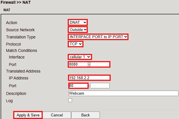
The device is now accessible via the router’s public IP + mapped port.

MAC-IP Binding
Located under Firewall > MAC-IP Binding.
This feature ensures that devices can only access the router if their MAC and IP address match.
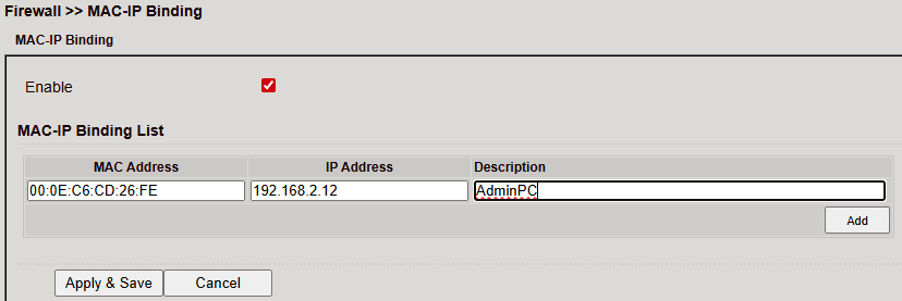
Parameter |
Description |
|---|---|
MAC Address |
Enter in format |
IP Address |
IP address assigned to the device, e.g. |
Description |
Optional description text |
QoS – Traffic Control
The Traffic Control page allows configuration of QoS rules to prioritize traffic.
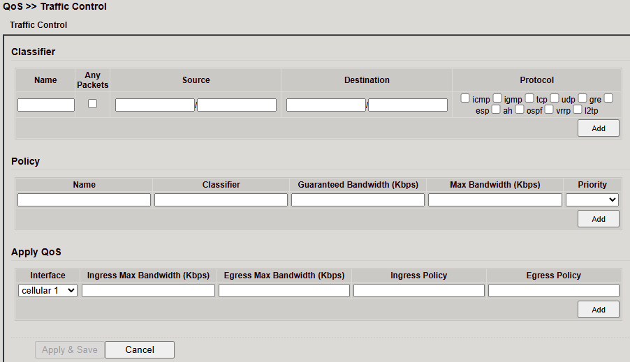
Classifier
Define criteria for traffic matching:
Name → Identifier
Source/Destination → IP or range
Protocol → TCP, UDP, ICMP
Click Add to save the classifier.
Policy
Assign bandwidth rules to a classifier:
Guaranteed Bandwidth → Minimum rate (Kbps)
Max Bandwidth → Maximum rate (Kbps)
Priority → Importance of traffic
Click Add to apply the policy.
Apply QoS
Assign policies to interfaces:
Interface → e.g., Cellular 1
Ingress/Egress Bandwidth → Max allowed rates
Ingress/Egress Policy → Selected policy
Click Add, then Apply & Save.
VPN
VPN (Virtual Private Network) connects devices securely to remote networks.
Example: Remote employees accessing the company LAN from home.
IPsec
IPsec (Internet Protocol Security) is a protocol suite that secures communication at the network level by providing:
Integrity
Authentication
Confidentiality
Anti-replay protection
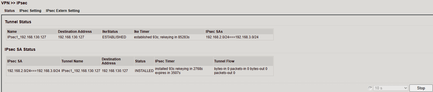
Status
If the tunnel is established, status shows active connection(s).
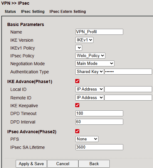
IPsec Setting
Configure under VPN > IPsec > IPsec Setting.
Steps:
Create IKE policy (v1 or v2).
Create IPsec policy.
Save via Apply & Save.
Create the actual IPsec tunnel.
IKEv1 Policy
Parameter |
Description |
|---|---|
ID |
Unique identifier (integer) |
Encryption |
Selected encryption method |
Hash |
Hash algorithm |
Diffie-Hellman Group |
DH group for key exchange |
Lifetime |
Validity period before renegotiation |
IKEv2 Policy
Parameter |
Description |
|---|---|
ID |
Unique identifier (integer) |
Encryption |
Selected encryption method |
Hash |
Hash algorithm |
Diffie-Hellman Group |
DH group for key exchange |
Lifetime |
Validity period before renegotiation |
IPsec Policy
Parameter |
Description |
|---|---|
Name |
Identifier for the policy |
Encapsulation |
ESP or AH |
Encryption |
Encryption method |
Authentication |
Hash algorithm |
IPsec Mode |
Tunnel or Transport mode |
IPsec Tunnel
Create tunnel under VPN > IPsec > IPsec Setting > IPsec Tunnels.
⚠️ Requires existing IKE (v1/v2) and IPsec policy.
Basic Parameters
Parameter |
Description |
|---|---|
Destination Address |
Remote peer IP |
Map Interface |
Local interface used |
IKE Version |
IKEv1 or IKEv2 |
IKEv1 Policy |
ID of the previously created IKEv1 policy |
IPsec Policy |
Name of the IPsec policy |
Negotiation Mode |
Main Mode or Aggressive Mode |
Authentication Type |
Shared Key or Certificate |
Local Subnet |
Local LAN subnet |
Remote Subnet |
Remote LAN subnet |
IKE Advanced (Phase 1)
Parameter |
Description |
|---|---|
Local ID |
IP Address, FQDN or User FQDN |
Remote ID |
IP Address, FQDN or User FQDN |
IKE Keepalive |
Enable/disable IKE Keepalive |
DPD Timeout |
Timeout for a Dead Peer Detection packet |
DPD Interval |
Interval of DPD packets |
XAUTH |
Enable/disable Extended Authentication |
XAUTH Username |
Username for XAUTH |
XAUTH Password |
Password for XAUTH |
IPsec Advanced (Phase 2)
Parameter |
Description |
|---|---|
PFS |
Perfect Forward Secrecy group |
IPsec SA Lifetime |
Validity period of Security Association before renewal |
IPsec SA Idletime |
Time before inactive SAs are deleted (prior to global lifetime) |
Tunnel Advanced Parameters
Parameter |
Description |
|---|---|
Tunnel Start Mode |
Default = Automatic |
Local Send Cert Mode |
Defines when to send the certificate |
Remote Send Cert Mode |
Defines when the peer must send its certificate |
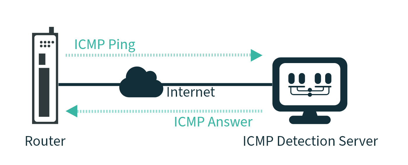
ICMP Detect |
Enable/disable ICMP watchdog |
ICMP Detection Server |
Server used to test tunnel reachability (reachable only via tunnel) |
ICMP Detection Local IP |
Local router interface IP |
ICMP Detection Interval |
Interval for ICMP tests |
ICMP Detection Timeout |
Timeout for ICMP responses |
ICMP Detection Max Retries |
Maximum retries after failed ICMP pings |
IPsec External Setting
Profiles are required for GRE over IPsec. Create a profile with Add.
Parameter |
Description |
|---|---|
Name |
Unique profile name |
IKE Version |
IKEv1 or IKEv2 |
IKEv1 Policy |
ID of the IKEv1 policy |
IPsec Policy |
Name of the IPsec policy |
Negotiation Mode |
Main or Aggressive |
Authentication |
Shared Key or Certificate |
IKE Advanced (Phase 1)
Parameter |
Description |
|---|---|
Local ID |
IP Address, FQDN, or User FQDN |
Remote ID |
IP Address, FQDN, or User FQDN |
IKE Keepalive |
Enable/disable Keepalive |
DPD Timeout |
Timeout for DPD packet |
DPD Interval |
Interval for DPD packets |
IPsec Advanced (Phase 2)
Parameter |
Description |
|---|---|
PFS |
Perfect Forward Secrecy group |
IPsec SA Lifetime |
Validity period before SA is recreated |
Fail Times to Restart Interface |
Failed attempts before restarting interface |
Fail Times to Reboot |
Failed attempts before router reboot |
Tunnel
VPN tunnels enable secure communication between networks or devices.
Tunnel Entry
Overview table shows:
Interface Type
Local/Remote Virtual IP
Peer Address
IPsec Profile
Description
Use Add to create, or Modify/Delete to manage.
Tunnel Configuration
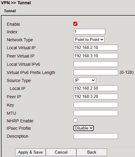
Options when adding/editing:
Enable – Activate tunnel
Index – Unique identifier
Network Type – e.g. Point-to-Point
Local/Peer Virtual IP – Virtual tunnel endpoints
Local/Peer IP – Physical endpoints
Key – Shared key if required
MTU – Max transmission unit
NHRP Enable – Enable Next Hop Resolution Protocol
IPsec Profile – Select encryption/auth profile
Description – Optional
Click Apply & Save to activate.
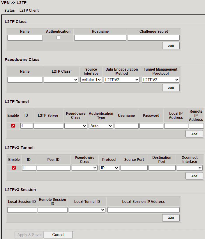
L2TP
L2TP (Layer 2 Tunneling Protocol) combines PPTP and L2F.
Provides tunneling, but no encryption → must be paired with IPsec.
Often used for single-user connections (road warrior).
L2TP Status
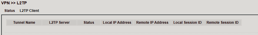
L2TP Client
Configure under VPN > L2TP > L2TP Client.
Add entries via Add
Save with Apply & Save
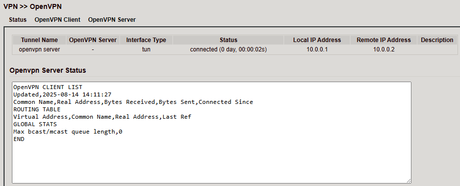
OpenVPN
OpenVPN is open-source VPN software using TLS/SSL encryption.
Transport: UDP or TCP
Encryption via OpenSSL
OpenVPN Status
Client Status
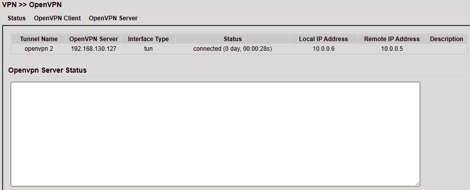
Server Status
OpenVPN Client
Configure under VPN > OpenVPN > OpenVPN Client.
Create a new tunnel with Add.
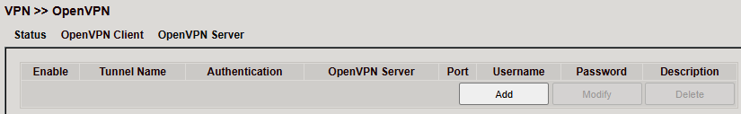
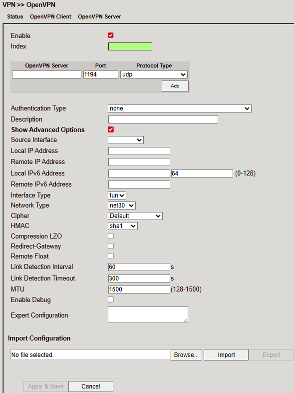
Parameters:
Parameter |
Description |
|---|---|
Enable |
Enable/disable tunnel |
Index |
Identifier for tunnel |
OpenVPN Server |
IP/FQDN of OpenVPN server |
Authentication Type |
Method (recommended: |
Username |
Username |
Password |
Password |
Description |
Optional description |
Show Advanced Options
Parameter |
Description |
|---|---|
Source Interface |
Interface used for tunnel |
Interface Type |
|
Cipher |
Encryption method |
HMAC |
Signs TLS handshake packets (default: SHA1) |
Compression LZO |
Enable/disable data compression |
Redirect-Gateway |
Route all traffic via tunnel |
Remote Float |
Accept packets even if server IP changes (useful for dynamic IP servers) |
Link Detection Interval |
Interval for connection checks |
Link Detection Timeout |
Timeout for connection checks |
MTU |
Maximum packet size |
TCPMSS |
Maximum size for TCP packets |
Fragment |
Maximum packet size for UDP |
Enable Debug |
Enable/disable debug mode |
Expert Configuration |
Raw OpenVPN options not available via GUI |
⚠️ The client always needs the server’s CA certificate.
You can import/export OpenVPN configurations (.ovpn files).
⚠️ Avoid spaces in filenames.
OpenVPN Server
Configure under VPN > OpenVPN > OpenVPN Server.
⚠️ A public IP is required.
Parameters:
Parameter |
Description |
|---|---|
Enable |
Enable/disable OpenVPN server |
Config Mode |
Manual configuration or import of an existing config |
Authentication Type |
Authentication method |
Virtual Network |
Virtual subnet for VPN clients |
Virtual Netmask |
Subnet mask for the VPN network |
Description |
Optional description |
Advanced Options
Parameter |
Description |
|---|---|
Source Interface |
Interface over which the OpenVPN tunnel is established |
Interface Type |
|
Network Type |
Connection type (recommended: |
Protocol Type |
UDP or TCP |
Port |
Port on which the OpenVPN server listens |
Cipher |
Encryption method |
HMAC |
Hash-based Message Authentication Code |
Client-to-Client |
Enable/disable communication between clients |
Compression LZO |
Enable/disable compression |
Link Detection Interval |
Interval for tunnel connection checks |
Link Detection Timeout |
Timeout for tunnel connection check packets |
MTU |
Maximum packet size |
TCPMSS |
Maximum size for TCP packets |
Fragment |
Maximum packet size for UDP packets |
Enable Debug |
Enable/disable debug mode |
Expert Configuration |
Enter custom OpenVPN options not available via web interface |
User Password
Clients can be added here. Each client logs in with a username and password.
Local Subnet
Defines which local subnets of the router are accessible for clients.
Client Subnet
Defines which client subnets are accessible from the server.
Client ID = Username (for User/Password auth) or CN (for certificate auth).
⚠️ The OpenVPN server requires a CA certificate, public key and private key (uploaded under VPN > Certificate Management).
If these are missing, the server will not start.
Certificate Management
Used to store certificates for IPsec and OpenVPN (unless using PSK).
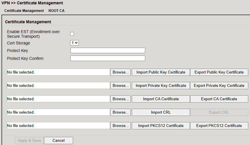
Click Browse, select the certificate file and Import.
Use Export to verify upload (file size > 0 bytes).
If upload fails, try another browser/PC.
If importing a PKCS12 set with password → enter password in Protect Key + Protect Key Confirm.
Click Apply & Save.
Parameter |
Description |
|---|---|
Enable SCEP |
Enable Simple Certificate Enrollment Protocol for auto-rollout |
Protect Key / Confirm |
Password for password-protected certificates |
Revocation |
Enable certificate revocation list (CRL) |
Import Public Key Certificate |
Upload public key certificate |
Import Private Key Certificate |
Upload private key certificate |
Import CA Certificate |
Upload Certificate Authority certificate |
Import CRL |
Upload Certificate Revocation List |
Import PKCS12 Certificate |
Upload PKCS12 certificate set |
Industrial
Features:
Digital input
Relay output
RS-232 interface
RS-485 interface
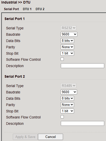
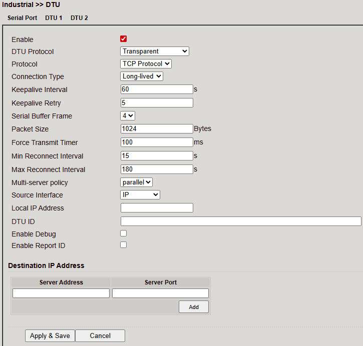
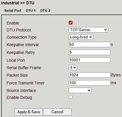
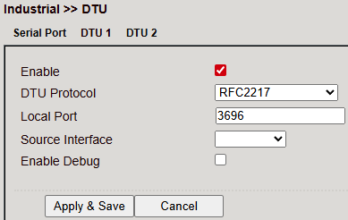
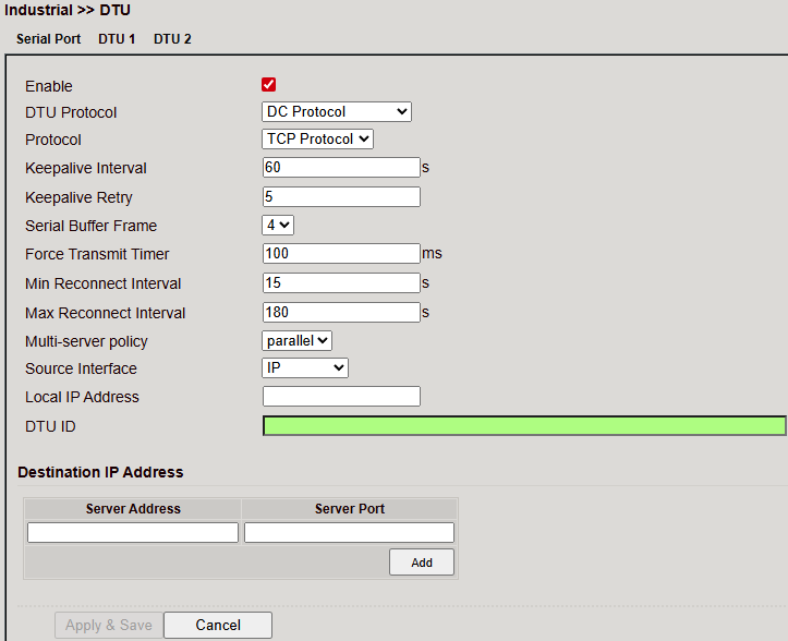
DTU (Data Terminal Unit)
Connects serial devices (RS-232, RS-485).
Configuration consists of two parts:
Serial Port properties (RS-232 / RS-485).
DTU Protocol Parameters.
Serial Port
Configure serial ports 1 (RS232) and 2 (RS485).
DTU Protocols
Transparent Mode
TCP Server
RFC2217
IEC60870-5-101/104
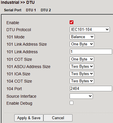
Modbus-Net-Bridge
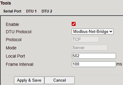
DC Protocol
Tools
Utilities for diagnostics and network tests.
Ping
Send ICMP echo requests.
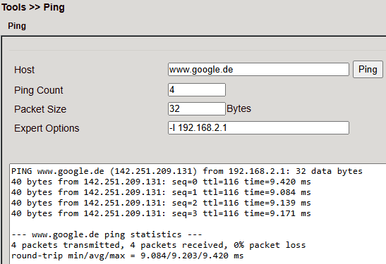
Parameter |
Description |
|---|---|
Host |
Destination IP/hostname |
Ping Count |
Number of pings (1–50, default: 4) |
Packet Size |
Packet size (default: 32 bytes) |
Expert Options |
Additional advanced settings |
Traceroute
Displays routing path to a host.
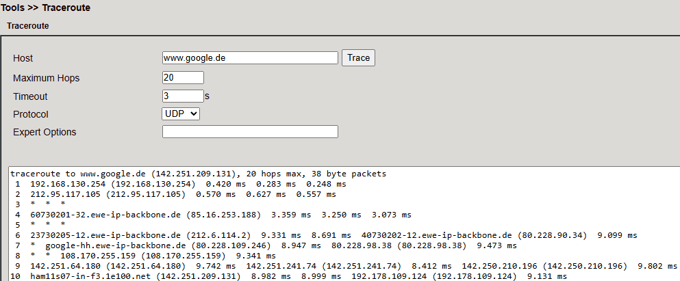
Parameter |
Description |
|---|---|
Host |
Destination IP/hostname |
Maximum Hops |
Hop limit (2–40, default: 20) |
Timeout |
Timeout per hop (2–10s) |
Protocol |
ICMP or UDP (default: UDP) |
Expert Options |
Advanced options |
Tcpdump
Packet sniffer for TCP/UDP analysis.
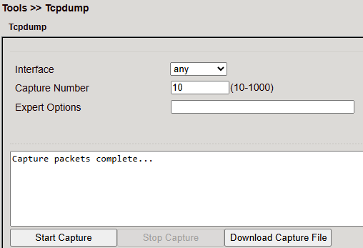
Parameter |
Description |
|---|---|
Interface |
Interface to capture |
Capture Number |
Number of packets (default: 10) |
Expert Options |
Advanced options |
Start Capture |
Begin packet capture |
Stop Capture |
Stop packet capture |
Download Capture File |
Save capture as |
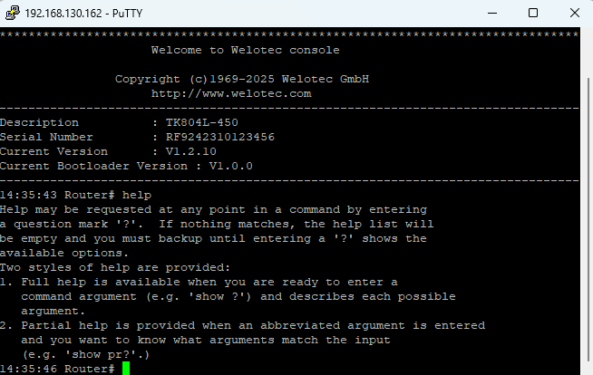
CLI Commands
The router can also be managed via CLI (Command Line Interface) using SSH or Telnet.
Enable under Administration > Management Services.
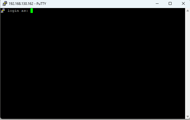
Use a terminal client such as PuTTY.
Connection
Enable SSH/Telnet in the router (Apply & Save).
Start PuTTY, enter router IP, select SSH/Telnet.
Connect.
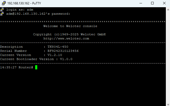
Default login:
User:
admPassword:
123456
Help Command
help→ Shows help usage?→ Context-sensitive help at any point
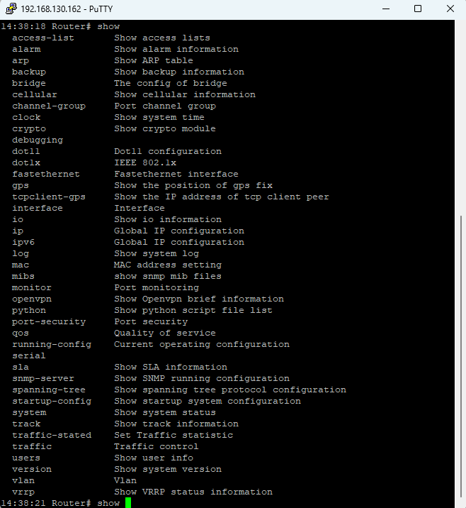
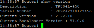
Show Command
Displays router parameters/config.
Example:
show version → Device info, serial no., firmware, bootloader.
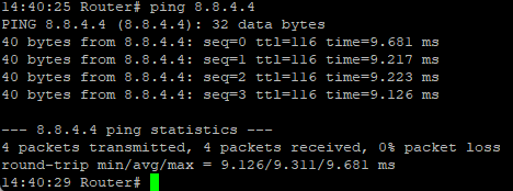
Ping Command
Check Internet connectivity.
ping <hostname/IP>
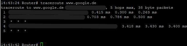
Traceroute Command
Test the active routing path to a destination.
traceroute <hostname/IP>
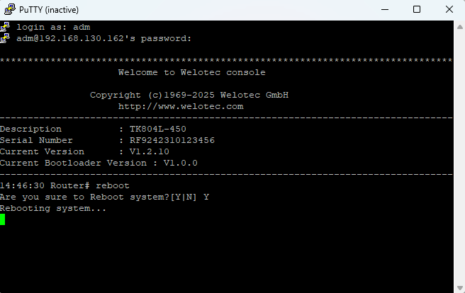
Reboot Command
To restart the router, you can use the reboot command. Enter it in the CLI and the router will be restarted.
Configuration Command
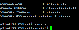
In the superuser view, the router can use the configure command to switch the configuration view for management. A configure command can support no and default, where no indicates setting the abort of a parameter and default indicates restoring the default setting of a parameter. The configure terminal (or conf t for short) command switches the system to configuration mode. In this setting the router can be configured. To exit the configuration mode use the exit command. All entered commands must be terminated with the wr command so that the changes are applied to the router.
Hostname Command
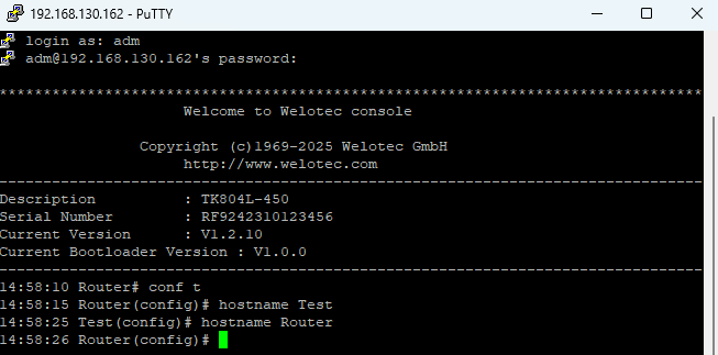
In configuration mode, you can change the router name using hostname
This sets the router’s name to the value you specify.
To reset the router name back to the factory default, use default hostname.
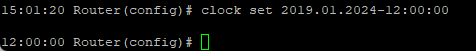
Clock Set Command
You can configure the system date and time of the router using the clock set command.
The required format is: YYYY.MM.DD-HH:MM:SS
Example: clock set 2019.01.24-12:00:00
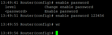
Enable Password Command
The password of the superuser (adm) can be changed at any time via the CLI.
Use the command: enable password
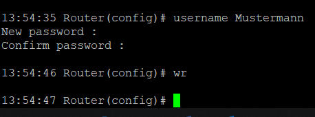
Username Command
The username command allows you to create new users for router access.
Syntax: username
When creating the user, you will be prompted to set a password.
⚠️ New users created this way are always standard users (not administrators).